Project Overview
The Hyperloop Technical Design Report was submitted to the Teknofest Aviation, Space, and Technology Festival as part of our Hyperloop Development Competition project. This report documents the entire design process—from the initial capsule design to the detailed analyses of propulsion, levitation, braking, and thermal management systems. It also covers the integration of advanced sensors and communication networks to ensure safe and efficient operation.
1. Capsule Design, Analysis & Production
1.1 Capsule Specifications
- Length: 1355 mm
- Width: 720 mm
- Height: 360 mm
- Approximate Weight: ~106 kg
- Materials:
- Chassis & Shell: Carbon Steel, Steel, Carbon Fiber, and Epoxy Panels
- Brake Pads: Ceramic-Carbon (HRC 65)
1.2 Detailed Design Summary
Our design process focused on ensuring that all subsystems operate as an integrated whole. Key aspects include:
- Component Integration:
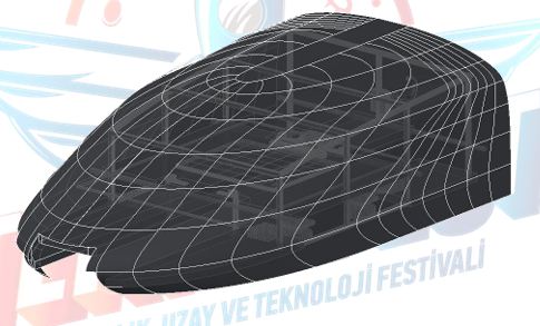
The capsule design integrates multiple subsystems such as navigation, propulsion, levitation, braking, and cooling. - CAD Modeling & Technical Drawings:
Detailed SolidWorks CAD models and technical drawings were created to guide manufacturing and assembly. - Connection Mechanism:
A hook-like connection device was designed to allow for emergency extraction if the capsule becomes immobilized.
Example Diagram:
2. Power Consumption & Energy Sources
The capsule is powered exclusively by Lithium Polymer (Li-Po) batteries configured as follows:
- Propulsion:
- 4 × POWER-XTRA 22.2V 6S1P 5000 mAh (40C) cells in series yield approximately 88.8V.
- With an estimated current draw of 106.4A, the propulsion system can operate for roughly 3 minutes under peak conditions.
- Levitation:
- 3 × POWER-XTRA 11.1V 3S1P 2700 mAh (20C) cells in parallel provide an 11.1V 8100mAh pack, giving around 7 minutes of operation.
- Auxiliary Systems:
- A single POWER-XTRA 7.4V 2S1P 3300 mAh (55C) battery supports low-power electronic components.
3. Navigation System & Sensor Integration
The navigation system employs multiple sensors to ensure precise control:
- 10 DOF MEMS IMU Sensor:
Measures acceleration, orientation, and gravitational forces. - APDS-9960 RGB Sensor:
Detects ambient light, color, and proximity. - Additional Sensors:
Includes US1881 Hall Effect sensors, SHT35 Temperature & Humidity sensors, and a TF03 LiDAR sensor.
These sensors provide real-time data to the control system, allowing the capsule to adjust its course and maintain stability.
4. Levitation System
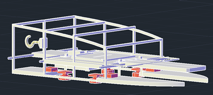
Our levitation system is based on rotating Halbach arrays arranged in a quadrupolar configuration:
- Design:
Four rotating Halbach arrays create a concentrated magnetic field that levitates the capsule. - Calculations:
Using Biot-Savart’s law, we determined that each array must produce a minimum force of approximately 260,715 N to achieve a 6 cm gap. - Performance:
At 1600 RPM (80 m/s), the system generates an estimated force of around 1410 N.
Levitation Diagram(orange):
5. Propulsion & Stability System
5.1 Propulsion
A three-phase linear induction motor is used to propel the capsule:
- Operating Principle:
The motor generates thrust via electromagnetic interaction, as described by the formula:
F = I × (L × B) - Performance:
With a calculated force of 315 N and a target speed of 30 m/s, the propulsion system meets the design requirements. - Power Consumption:
The power requirement is estimated using P = F × V.
5.2 Stability
To ensure the capsule remains stable:
- Braking System:
A combination of magnetic and mechanical braking (using servo-actuated ceramic-carbon brake pads) is implemented. - Wheel Assemblies:
Additional wheels provide stability during low-levitation phases.
6. Aerodynamic, Thermal & Vacuum Analyses
6.1 Aerodynamic Analysis
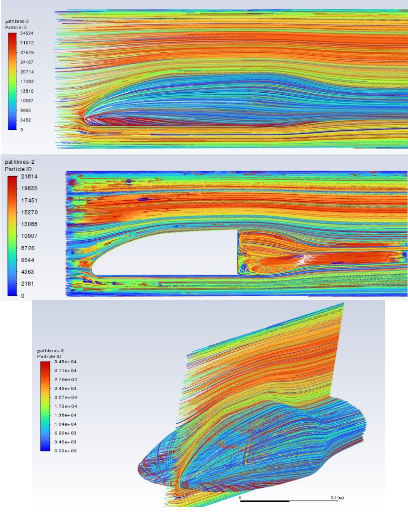
CFD simulations were performed using a k-Omega SST turbulence model at 100 km/h:
- Drag & Lift Forces:
Detailed analyses determined the drag and lift coefficients, which were used to optimize the capsule’s streamlined shape.
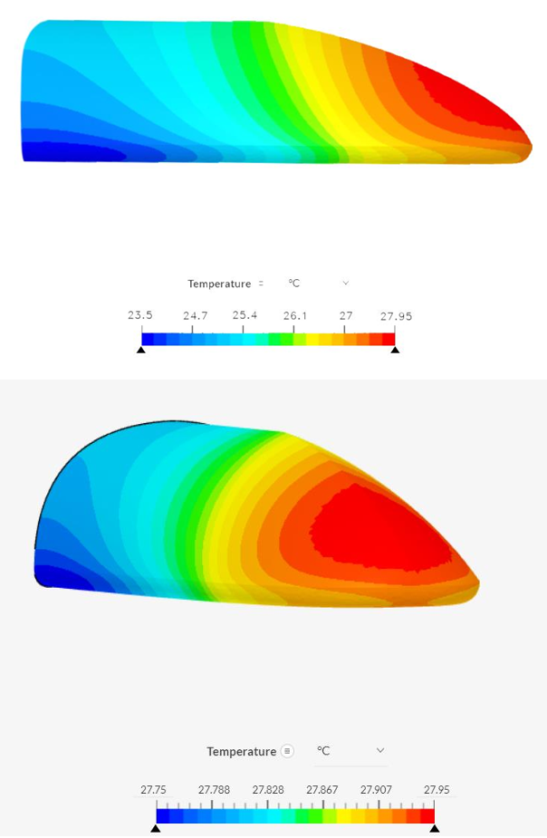
6.2 Thermal Analysis
A liquid cooling system maintains operational temperatures:
- Cooling Components:
A radiator, DC water pump, tubing, and glycerin are used to dissipate heat. - Heat Transfer:
The system is designed to handle approximately 2140 Joules of heat, resulting in a temperature increase of around 6.2 °C for critical components.
6.3 Vacuum Analysis
The design ensures stable operation under low-pressure conditions typical of Hyperloop systems.
Simulation Images:
7. Safety Systems & Emergency Procedures
To safeguard the capsule during operation, several safety features are integrated:
- Emergency Braking:
A secondary braking mechanism using servo-actuated ceramic-carbon brake pads. - Liquid Cooling:
Prevents overheating of vital components. - Remote Shutdown:
A control system enables remote deactivation in emergencies. - Emergency Extraction:
A hook-like connection device allows the capsule to be safely removed from the track in case of failure.
8. Communication & Control
The capsule’s control system ensures seamless communication between subsystems:
- Interconnectivity:
Multiple microcontrollers (Arduino Mega, STM32, and Raspberry Pi) communicate via CAN Bus. - Wireless Data Transmission:
Sensor data is relayed via Wi-Fi to a remote control center. - User Interface:
Real-time monitoring displays parameters such as position, speed, acceleration, and temperature.
9. Theoretical Maximum Speed & Budget Analysis
9.1 Theoretical Speed
Calculations based on the propulsion and levitation systems indicate that the capsule could achieve competitive speeds in a high-speed transit system.
9.2 Budget Overview
A detailed budget breakdown covers material costs, manufacturing expenses, and testing, ensuring the design remains financially viable.
Appendix
For a more detailed review, download the full technical report here.
