
SIMPLE PROGRAMMABLE ROBOTIC ARM
Mechatronics Engineering, Istanbul Bilgi University, 2022
ABSTRACT
Modern industry heavily relies on robots and mechanical systems to increase efficiency, yet smaller-scale projects can also bring convenience, education, or entertainment. Computers followed a similar path—from business applications to everyday home use. Today, resources for building small robotic projects are widely available. Our goal was to design and build a controllable, programmable robotic arm that illustrates these concepts on a smaller scale.
INTRODUCTION
To create a programmable robotic arm, we first needed foundational knowledge in programming, motors, and Arduino:
- Programming: The instructions (“brain”) that tells the robot what to do.
- Motors: We used micro servo sg90 motors, which allow precise control of position, velocity, and torque—ideal for a small robotic arm.
- Arduino: An accessible microcontroller platform. According to Arduino’s own description, it enables people to easily access advanced technologies that interact with the physical world.
By combining these elements, we aimed to demonstrate a simplified example of how more complex industrial robotic arms function.
METHODOLOGY
1. Project Planning & Research
We began by browsing project forums (like Hackster.io) and discussing ideas that balanced complexity and feasibility for a first university project. We ultimately chose a programmable robotic arm because it would be both instructive and fun to build.
2. Motor Selection
We needed motors that could precisely control position in three axes:
- Affordability
- Availability
- Suitability for a small robotic arm
After researching, we chose micro servo sg90 motors.
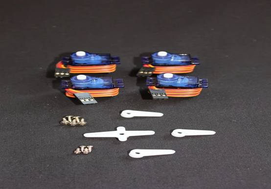
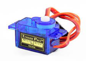
(Left) A set of micro servo sg90 motors. (Right) Close-up of a single Tower Pro SG90 servo.
3. Arduino Basics
Although our Arduino experience was limited, we leveraged school lessons, online forums, and YouTube tutorials to gain confidence. Arduino’s large community and ready-to-use libraries made the learning curve more manageable.
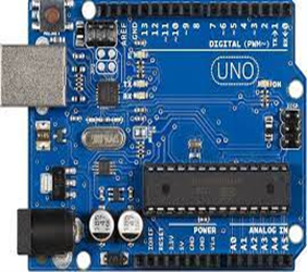
(An Arduino Uno, the microcontroller we used for controlling servos.)
4. Circuit Diagram
Below is the wiring setup, showing how servos connect to Arduino PWM pins and how potentiometers (or a joystick) provide analog input for controlling the arm:
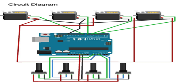
(Circuit diagram with four servos and four potentiometers wired to the Arduino.)
5. Robotic Arm Structure
5.1 Cardboard vs. 3D Printing
We considered cardboard (simple but fragile) and 3D printing (sturdier and more precise). Ultimately, we chose 3D printing for durability and accuracy.
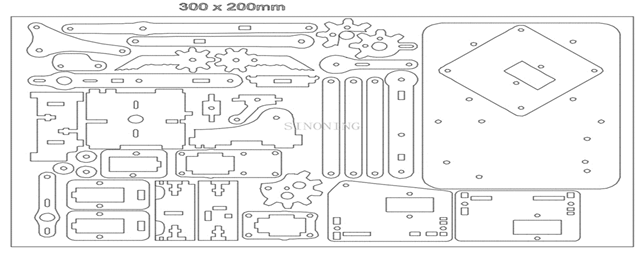
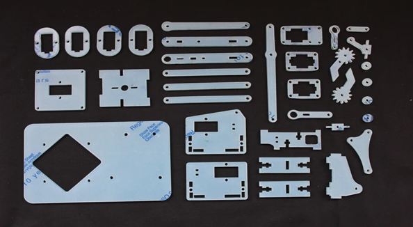
(Left) Layout of the parts on a 300×200mm sheet. (Right) All acrylic/3D-printed pieces cut and ready for assembly.
5.2 Schema & Example
Below is a schematic layout of the arm components, plus an example of how it looks when fully assembled:
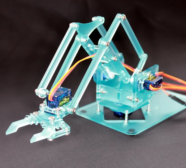
(Left) Various acrylic parts for the arm. (Right) Final assembled arm with servos.)
6. Assembly Steps
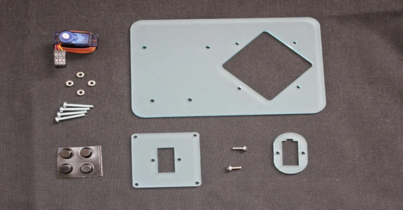
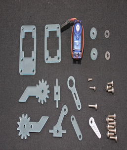
6.1 Prepare the Base
We started by gathering the base plate, servo, and hardware:
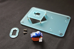
Base pieces
- Attach sticky feet (if included) to each corner of the base.
- Insert screws into the base plate, half-tightening nuts to hold them in place.
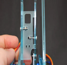
6.2 Add the Square
Next, we added the raised square platform on top of the base, using standoffs:
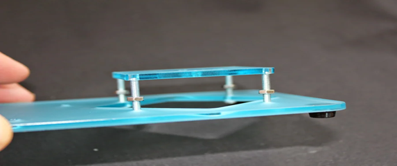
(Left) Standoffs partially installed. (Right) Servo fitted into the top square plate.
- Align the square plate’s holes with the screws from the base.
- Tighten screws until flush, ensuring a stable platform.
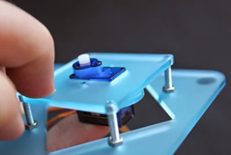
6.3 Collar the Servo
We found that adding collars to the servos was the best way to secure them:
- Thread the servo wire through the collar.
- Line up the collar’s cutout with the servo’s wire attachment point.
- Press until it’s flush with the servo flange.
(See “Prepare the Base” images for reference.)
6.4 Build Your First Levers
We then attached the servo horns to lever parts:
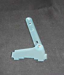
(An acrylic lever piece with a pivot screw.)
- Use the long servo screw to attach the white plastic horn to the lever.
- Connect the long lever piece, ensuring minimal friction.
6.5 Bringing the Parts Together
This step involved assembling the side frames and inserting the “pig” piece:
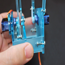
(Left) Side pieces partially assembled. (Right) Close-up of the central base with side attachments.)
- Loosely attach the end cradle pieces with 12mm screws.
- Insert the “pig” between the cutouts, tightening screws gently so everything fits.
6.6 The Claw & Jaws
Finally, we built and attached the claw:
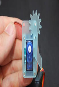
(Left) Claw parts and gears laid out. (Right) A servo with an attached gear.)
- Assemble the claw mechanism with gears.
- Attach it to the arm’s wrist using 8mm and 10mm screws.
RESULTS AND DISCUSSION
- Arduino & Servo Control: We used four micro servo sg90 motors to control the arm’s joints. Thanks to Arduino’s straightforward libraries, programming was simpler than expected.
- Mechanical Assembly: The 3D-printed parts proved more robust than cardboard, though we had to be careful with screw tightening to maintain smooth motion.
- Challenges:
- Over-tightening certain screws limited movement.
- One servo motor failed, requiring replacement and reassembly.
Overall, the project successfully demonstrated basic robotic arm motion in multiple axes, suitable for educational demonstrations or light tasks.
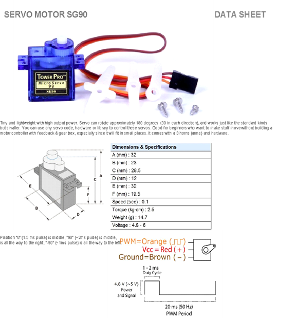
((Left) Micro servo SG90. (Right) Servo datasheet excerpt.)
CONCLUSION
This Simple Programmable Robotic Arm showcases a practical introduction to robotics, blending mechanical design, electronics, and coding. While industrial arms are far more complex, our small-scale version demonstrates the core principles of position control, torque management, and collaborative design. With stronger materials and more advanced programming, the arm could handle heavier loads or perform more intricate tasks.
APPENDIX: ARDUINO CODE
#include <Servo.h>

Servo servo1;
Servo servo2;
Servo servo3;
Servo servo4;

int z_key = A3;
int s_key = A4;
int x_key = A1;
int y_key = A0;
int x_pos;
int y_pos;
int z_pos;
int s_pos;
int servo3_pin = 6;
int servo4_pin = 10;
int servo1_pin = 11;
int servo2_pin = 9;
int initial_position = 90;
int initial_position1 = 90;
int initial_position2 = 90;
int initial_position3 = 90;

void setup() {
  Serial.begin(9600);
  servo1.attach(servo1_pin);
  servo2.attach(servo2_pin);
  servo3.attach(servo3_pin);
  servo4.attach(servo4_pin);
  servo1.write(initial_position);
  servo2.write(initial_position1);
  servo3.write(initial_position2);
  servo4.write(initial_position3);
  pinMode(x_key, INPUT);
  pinMode(y_key, INPUT);
  pinMode(z_key, INPUT);
  pinMode(s_key, INPUT);
}

void loop() {
  x_pos = analogRead(x_key);
  y_pos = analogRead(y_key);
  z_pos = analogRead(z_key);
  s_pos = analogRead(s_key);

  // Servo 1
  if (x_pos < 300) {
    if (initial_position >= 10) {
      initial_position -= 20;
      servo1.write(initial_position);
      delay(100);
    }
  }
  if (x_pos > 700) {
    if (initial_position <= 180) {
      initial_position += 20;
      servo1.write(initial_position);
      delay(100);
    }
  }

  // Servo 2
  if (y_pos < 300) {
    if (initial_position1 >= 10) {
      initial_position1 -= 20;
      servo2.write(initial_position1);
      delay(100);
    }
  }
  if (y_pos > 700) {
    if (initial_position1 <= 180) {
      initial_position1 += 20;
      servo2.write(initial_position1);
      delay(100);
    }
  }

  // Servo 3
  if (z_pos < 300) {
    if (initial_position2 >= 10) {
      initial_position2 -= 20;
      servo3.write(initial_position2);
      delay(100);
    }
  }
  if (z_pos > 700) {
    if (initial_position2 <= 180) {
      initial_position2 += 20;
      servo3.write(initial_position2);
      delay(100);
    }
  }

  // Servo 4
  if (s_pos < 300) {
    if (initial_position3 >= 10) {
      initial_position3 -= 20;
      servo4.write(initial_position3);
      delay(100);
    }
  }
  if (s_pos > 700) {
    if (initial_position3 <= 180) {
      initial_position3 += 20;
      servo4.write(initial_position3);
      delay(100);
    }
  }
}