UAV Flight Dynamics Simulator
A modern, interactive web application for simulating and analyzing the flight dynamics of fixed-wing UAVs. Designed for aerospace engineers, researchers, and students, this tool provides deep insight into how control inputs affect UAV behavior—both in longitudinal (4DOF) and full (6DOF) motion.
🌟 Key Features
- Dual Simulation Modes: 4DOF (longitudinal) and 6DOF (full motion)
- Interactive UI: Responsive, dynamic controls and visualization
- Real-time Visualization: Plot all state variables and control responses
- Stability Analysis: Eigenvalue analysis with mode identification
- Customizable UAV Parameters: Edit and save aircraft data
- Multiple Control Inputs: Define pulses for elevator, aileron, rudder, and throttle
✈️ Supported UAV Models
| UAV Name | Manufacturer | Country |
|---|---|---|
| TB2 | Baykar | Turkey |
| Anka | TUSAŞ | Turkey |
| Aksungur | TUSAŞ | Turkey |
| Karayel | Vestel | Turkey |
| Predator | General Atomics | USA |
| Heron MK1 | Israel Aerospace Industries | Israel |
| Heron MK2 | Israel Aerospace Industries | Israel |
Note: Some aerodynamic and inertial values are estimated from public data or literature. Lateral-directional derivatives for 6DOF are subject to estimation.
📐 Simulation Theory & Implementation
4DOF (Longitudinal Motion)
- State Vector:
[u, α, q, θ](forward speed, angle of attack, pitch rate, pitch angle) - Input Vector:
[thrust, elevator] - System: Linearized state-space: ẋ = A·x + B·u
- Integration: Runge-Kutta (scipy.solve_ivp)
6DOF (Full Motion)
- State Vector:
[u, v, w, p, q, r, φ, θ, ψ, x, y, z] - Input Vector:
[roll, pitch, yaw, throttle] - System: Nonlinear 6DOF equations, full inertia tensor, NED frame
🎮 Control Input System
- 4DOF: Elevator pulses (start, duration, angle)
- 6DOF: Roll, pitch, yaw, throttle pulses (all configurable)
- Multiple pulses supported; overlapping effects are combined at each timestep.
🖥️ User Interface & Workflow
- Select UAV and simulation mode (4DOF/6DOF)
- Edit parameters as needed
- Configure control pulses
- Set simulation duration
- Run simulation and analyze results
📊 Output Visualization
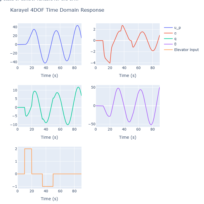
4DOF Example Results
Input:
- Duration: 90s
- Elevator Pulses: 10s/2°, 35s/-1°
Results:
- Trim Speed: U0 = 37.43 m/s
- Short Period: Highly damped (ζ = 0.763)
- Phugoid: Unstable (ζ = -0.050)
Time-Domain Plots:
4DOF Time Domain Plot
3D State-Space Trajectory:
4DOF 3D Trajectory
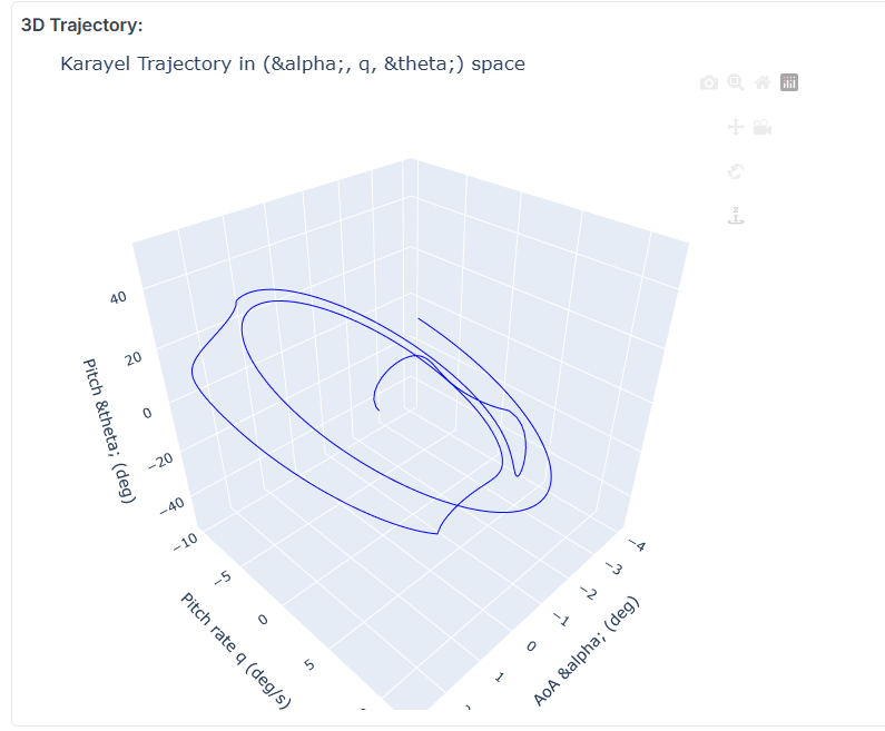
Interpretation:
- Short period mode damps quickly (good handling)
- Phugoid mode is unstable (oscillations grow over time)
- Plots show how elevator pulses affect speed, angle of attack, pitch rate, and pitch angle
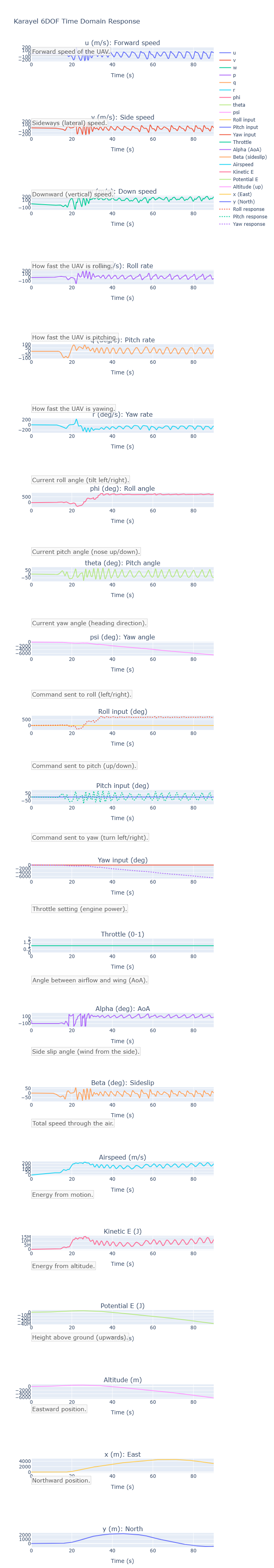
6DOF Example Results
Input:
- Duration: 90s
- Control Pulses: Multiple roll, pitch, yaw, throttle events
Results:
- Trim Speed: U0 = 37.43 m/s
- Eigenvalue analysis: Not implemented for 6DOF
Time-Domain Plots:
6DOF Time Domain Plot
3D Trajectory:
6DOF 3D Trajectory
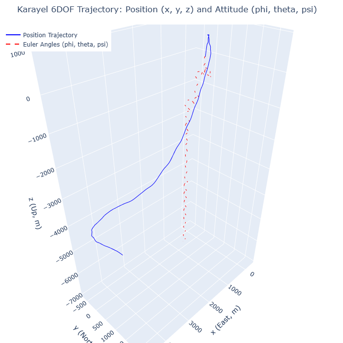
Interpretation:
- Full motion simulation: velocities, angular rates, attitude, position, and energy
- Visualizes both aircraft path and orientation in 3D
💡 Stability Analysis
- Short Period Mode: High frequency, pitch/angle of attack, critical for handling
- Phugoid Mode: Low frequency, speed/pitch angle, energy exchange
- Stability: Damping ratio (ζ) is computed for each mode; negative ζ means instability
⚙️ Technical Details
- UI: Reflex (Python web framework)
- Math Core: NumPy, SciPy
- Plots: Plotly
- State Management: Centralized simulation state class
- Responsive Design: Adapts to all screens
🚀 Get Started
- Clone the repo:
git clone https://github.com/daglar510/UAV_flight_dynamics_simulator.git - Install dependencies:
pip install -r requirements.txt - Run:
python -m reflex run - Open localhost:3000
⚠️ Limitations
- 4DOF mode uses linearized aerodynamics
- Some UAV parameters are estimated
- No wind/turbulence models
- Not flight-certified; for educational use
👨💻 Credits & Contact
- Original version: Mattia Di Mauro
- UAV extension, UI, 6DOF: Dağlar Duman
- GitHub Repository
-
Email LinkedIn
MIT License. Feel free to fork, use, or extend!