Project Overview
This project is a static structural verification + design optimization study for a conceptual 6-DOF robotic arm. The goal was not only to “prove it won’t fail,” but to right-size the structure using standard profiles so the design is realistic for manufacturing, weight, and cost.
Video Presentation
Design Requirements and Assumptions
Design targets (worst-case)
- Payload: 50 kg (treated as a tip load)
- Reach: 2.0 m from base axis to payload point
- Worst-case pose: arm fully horizontal (max gravitational moment)
- Safety requirement: FoS ≥ 2 (bending-driven)
Structural assumptions
- Static loading only (no impact, fatigue, vibration, or dynamics)
- Linear elastic material behavior
- Beam links treated using standard beam theory with conservative simplifications
- CAD non-beam masses included via an equivalent distributed load approach
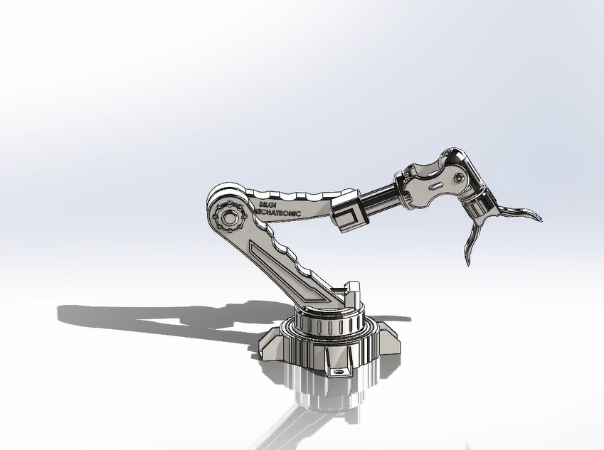
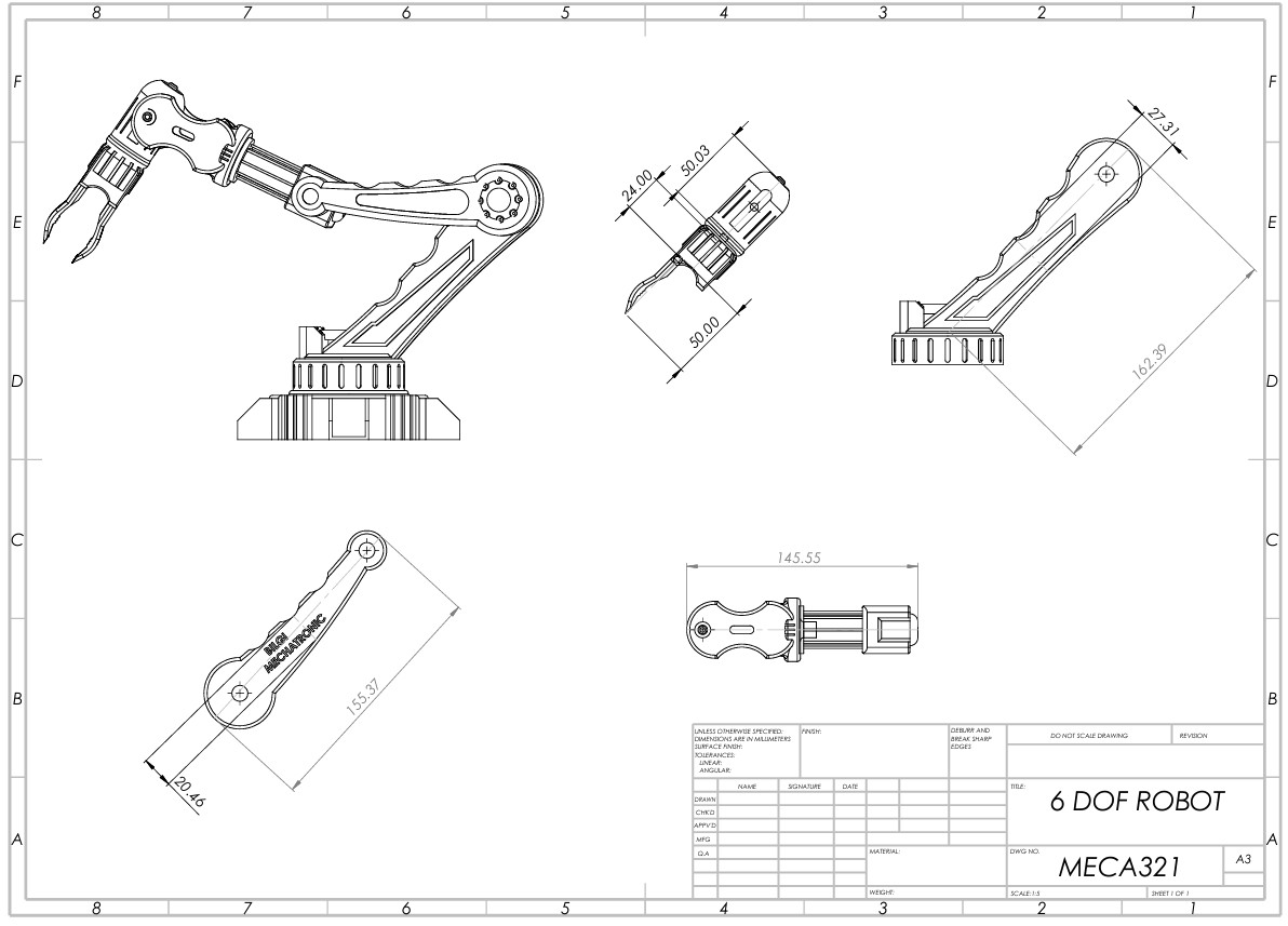
CAD Design (SolidWorks)
I first created the conceptual robotic arm geometry in SolidWorks, sized to meet the 2 m reach requirement. The CAD model defined the link layout and provided the physical basis for the structural simplifications used later.
Why this matters to recruiters: this step shows the ability to start from a realistic geometry and translate it into an analysis-ready mechanical model—exactly what happens in real engineering workflows.
Structural Modeling Approach
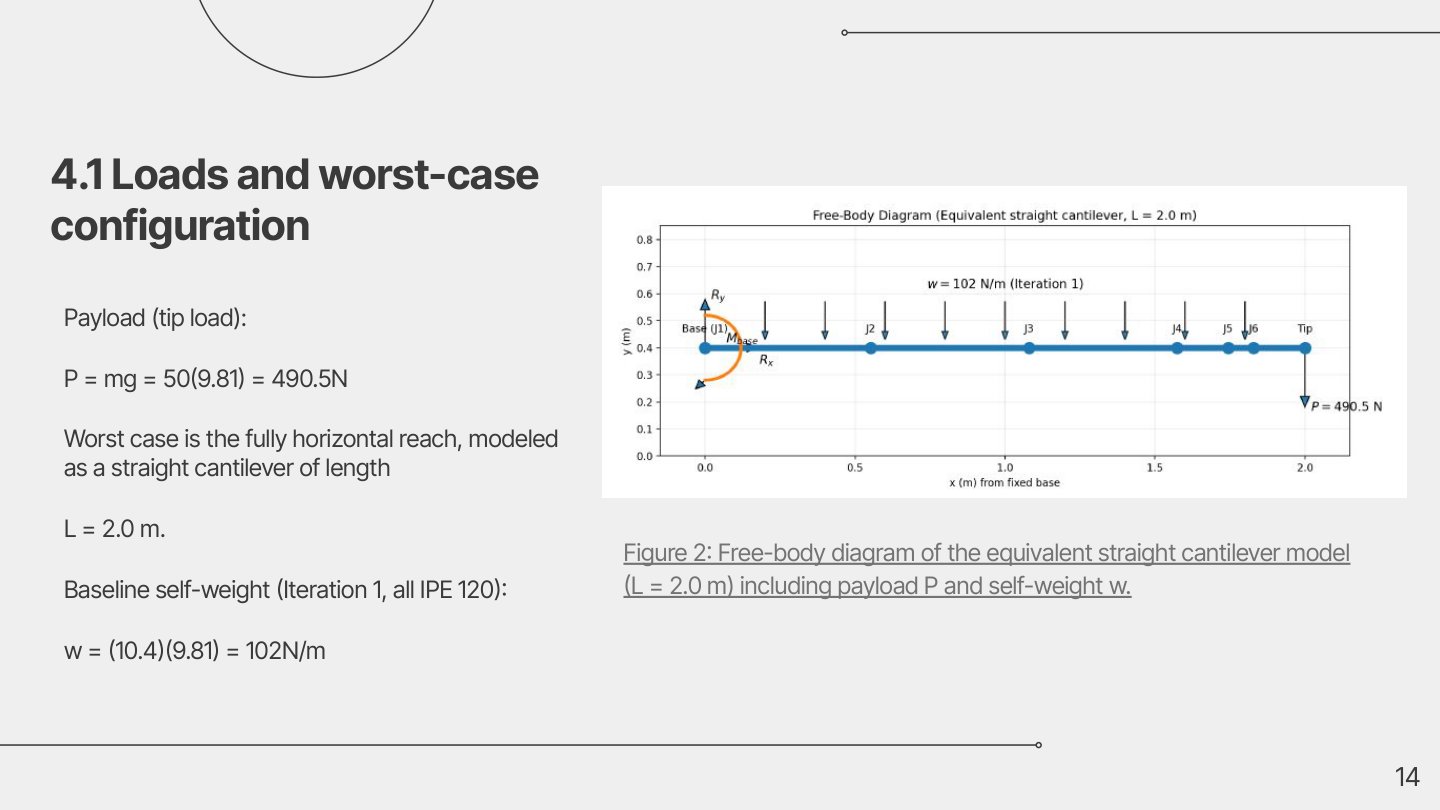
To make the problem solvable by hand while still being conservative, the robotic arm was converted into an equivalent straight cantilever beam that represents the worst-case load path.
- Tip payload modeled as: P = 50 × 9.81 = 490.5 N
- Self-weight captured as an equivalent distributed load
w(x)based on profile mass-per-meter - Internal actions derived: V(x) (shear) and M(x) (bending moment)
- Failure checks performed primarily using bending stress and deflection, with additional bounding checks for other modes
Core Hand Calculations (Shear, Moment, Stress, Deflection)
Loads used (baseline concept)
- Tip load: P = 490.5 N
- Example baseline distributed load (Iteration 1, IPE120):
w = (m' g) = (10.4 kg/m × 9.81) ≈ 102 N/m
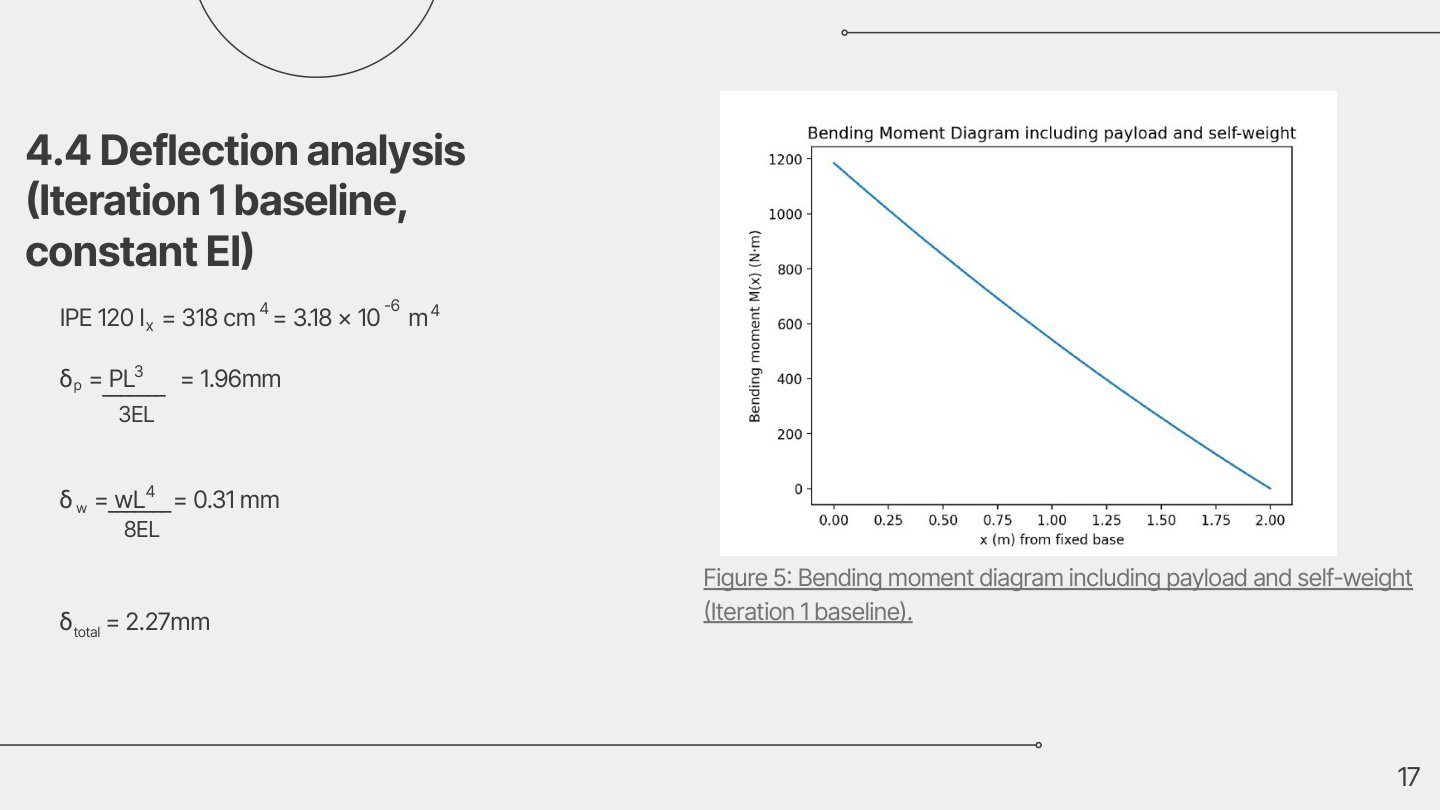
Shear and bending moment (general forms)
For a cantilever of length L with tip load P and distributed load w:
V(x) = P + w(L − x)M(x) = P(L − x) + (w/2)(L − x)^2
At the fixed base (x = 0), this produces maximum internal actions. For the baseline case (L = 2 m, P = 490.5 N, w ≈ 102 N/m):
V(0) ≈ 694.5 NM(0) ≈ 1185 N·m
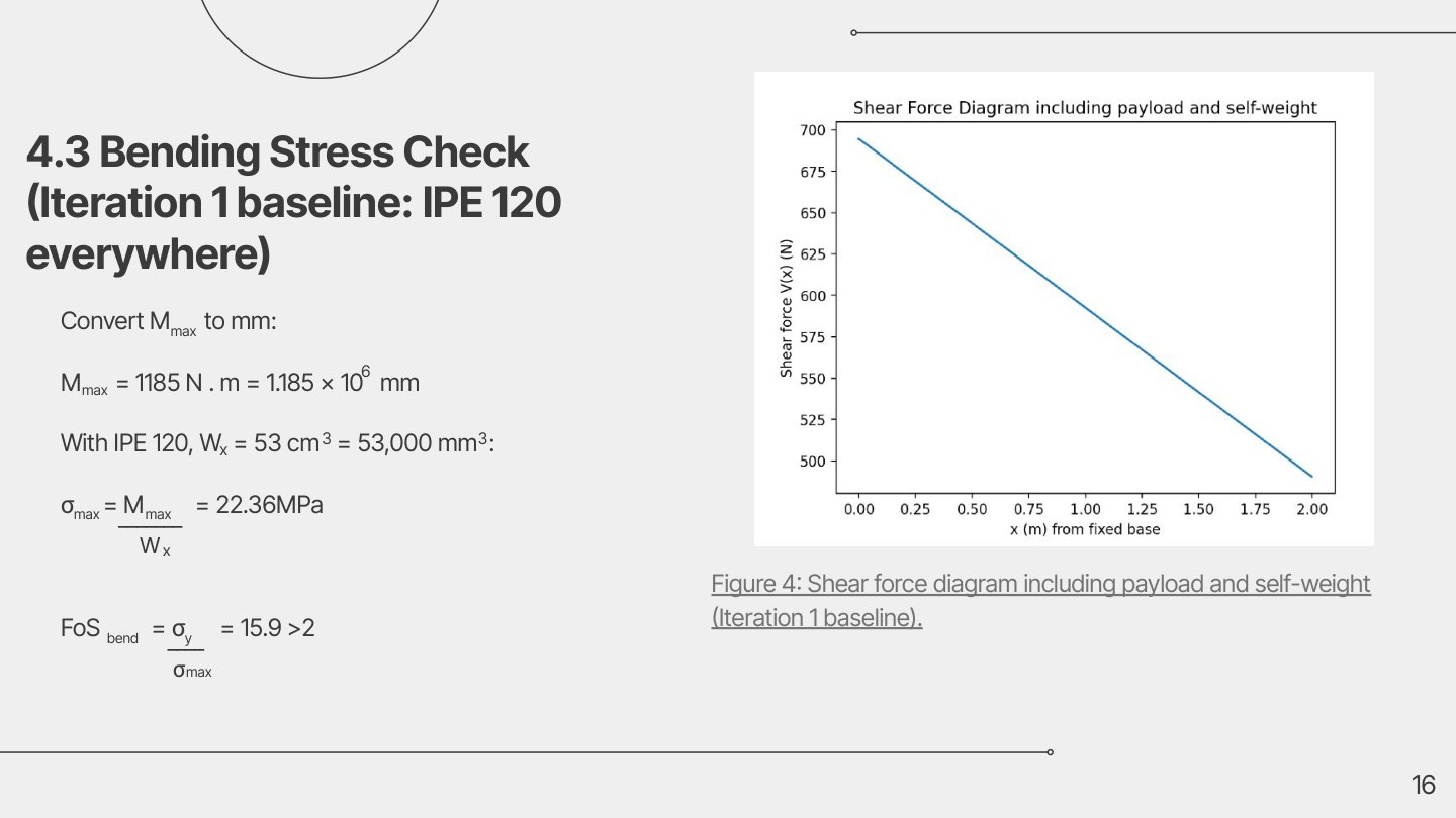
Bending stress check
Bending stress was computed using:
σ_max = M_max / W_x
For the baseline iteration (IPE120 everywhere), the resulting bending stress is very low relative to yield strength, indicating the first design is structurally conservative.
Deflection check
Deflection was computed by combining:
- deflection from the tip load
P - deflection from distributed load
w
The baseline design delivered very small tip deflection (millimeter-level), which is good structurally but often means the design is heavier than needed.
Iteration-Based Optimization (Standard IPE Profiles)
Instead of keeping an overbuilt section everywhere, the arm was optimized using industrial standard steel sections (IPE family).
The four evaluated iterations
- Iteration 1 (Baseline): IPE120 everywhere (very conservative)
- Iteration 2: reduced mass in distal links (moderate reduction)
- Iteration 3 (Final Selected): tapered IPE sections (largest reduction while keeping strong FoS)
- Iteration 4: minimum-cost strength-limited option (FoS ≈ 2 but very high deflection)
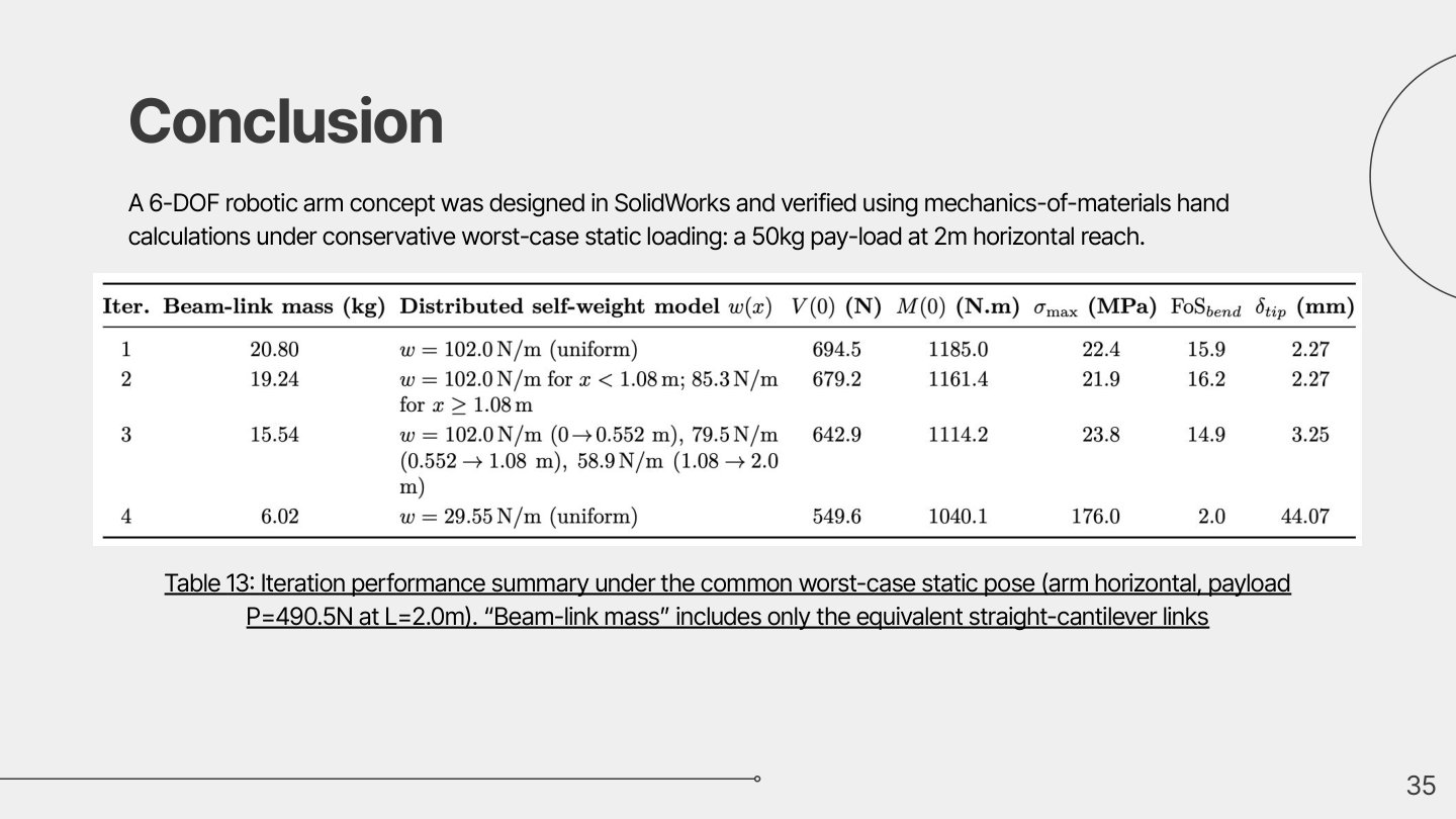
Performance summary (worst-case static pose)
| Iteration | Beam-link mass (kg) | V(0) (N) | M(0) (N·m) | σ_max (MPa) | FoS (bending) | δ_tip (mm) | |—:|—:|—:|—:|—:|—:|—:| | 1 | 20.80 | 694.5 | 1185.0 | 22.4 | 15.9 | 2.27 | | 2 | 19.24 | 679.2 | 1161.4 | 21.9 | 16.2 | 2.27 | | 3 | 15.54 | 642.9 | 1114.2 | 23.8 | 14.9 | 3.25 | | 4 | 6.02 | 549.6 | 1040.1 | 176.0 | 2.0 | 44.07 |
Final design decision (Iteration 3)
Iteration 3 was selected because it offers the best engineering trade-off:
- large mass + cost reduction versus the baseline
- still extremely safe in bending (FoS » 2)
- deflection stays in a realistic range compared to the very flexible “minimum-cost” limit case (Iteration 4)
Additional Failure Mode Checks (Bounding/Completeness)
Beyond bending, the design documentation also includes bounding checks to ensure the system remains safe under multiple failure modes typically expected in an arm structure, such as:
- shear stress bounds
- axial stress bounds
- torsion bounds
- buckling considerations
- joint / fastener sanity checks (e.g., base bolts)
This is important because real robotic arms are rarely “bending-only”—engineering credibility comes from checking the full envelope, even with conservative bounds.
Cost Perspective
A simple cost comparison was performed using a conservative material cost per kilogram and the computed beam-link masses. This was used to quantify the benefit of tapering the structure instead of overbuilding every link.
Project Files
Notes for Future Expansion
If this design were extended beyond static checks, the next realistic steps would include:
- dynamic loading and acceleration torque envelopes
- fatigue / duty-cycle considerations
- joint stiffness and bearing selection detail
- FEA validation (CAD-based) against the hand-calculation baseline